Labels

Tuesday, July 8, 2014

ROS Hydro SLAM with Kinect and iRobot Create

I have recently been trying to get into learning mapping with robotics and as a consequence I've been trying to get a SLAM (Simultaneous Localization And Mapping) algorithm running. Before investigating the mechanics and mathematics that cause SLAM to work, I wanted to get a known SLAM algorithm running so I can see it myself. With a laptop, Xbox Kinect, iRobot Create, and ROS, I knew I had all the tools I needed to get SLAM running.

The first step was to install ROS. Since Hydro is the newest version and has many drastic changes, I decided to go with it. Hindsight, that may have not been the best choice, but it's too late now! Also I am using Ubuntu 12.04, since Ubuntu is the officially supported OS and at the time, 12.04 is the LTS version that ROS supports.

Once ROS is installed, I had to get drivers for the iRobot Create and the Kinect, which were little adventures on there own with ROS Hydro and Ubuntu 12.04. See my posts on the Create. For the Kinect, I used the freenect stack, since it appears that openni (the most commonly used ROS-Kinect interface) has some issues with the hydro/Ubuntu 12.04 combination that I just didn't want to deal with.

Now that the sensor data is accessible, a SLAM algorithm can be selected. I went with gmapping, since it seemed to be the most widely used SLAM package on ROS. Gmapping requires odometry data, a laser scanner, and the position of the laser scanner relative to the base (create).

To fake a laser scanner with the Kinect, see my post here.

The odometry data and the odometry frame is published by the create node. The odom_frame is a standard frame from the tf package. The tf package allows the user to relate each part's coordinate frame to other coordinate frames on the robot. The primary coordinate frame that most everything needs to operate in relation to is the base_frame, which is provided by our Create. Tf wasn't the easiest thing for me to understand, and at the time of writing this, I still don't totally understand it.

To see each of your robot's coordinate frames, use:
rosrun tf view_frames
evince frames.pdf
tf view_frames will generate a pdf which displays your robot's tf tree. Each node in the tree is a separate coordinate frame, and each node in the same tree can access any other node's data with respect to the requesting node's frame.

So, gmapping needs to access the laser scanner's data with respect to the base_link frame. If you view your tf tree at this point, you will notice that the kinect's frames are not connected to the create's. To link the two, use:

rosrun tf static_transform_publisher "base_to_kinect" -0.115 0 0.226 0 0 0 base_link camera_link 100

This command creates a static transform between the kinect and the base. The numbers passed are the x,y,z coordinates of the kinect to the center of the create. If you view your tf tree after running the previous command you should get something that looks like this:


Now that all of the frames are linked, gmapping can be ran:

rosrun gmapping slam_gmapping tf_static:=tf

The tf_static:=tf renames gmapping's subscription to the /tf_static topic to the /tf topic. In ROS hydro the tf package has been deprecated, and now uses /tf2, which instead of just publishing one /tf topic, publishes a /tf and /tf_static. So, for gmapping to find the base_frame to link the map frame to, we have to redirect it to the /tf topic.

Once gmapping is running, you should be able to open up Rviz and see the data.

rosrun rviz rivz

Just be sure to add the map data from the /map topic to the display.


Monday, July 7, 2014

Faking a Laser Scanner in ROS Hydro using Kinect

I've been searching for a solution to fake a laser scanner using a kinect for ROS Hydro. The traditional method seems to be using the pointcloud_to_laserscan package, but unfortunately it hasn't been confirmed to work with ROS hydro. I also am using the freeneck_stack instead of the openni packages for interfacing with the kinect since I've had some trouble with it and apparently there are known problems with it and Ubuntu 12.04, which I am using.

The solution I'm using right now is the depthimage_to_laserscan package. It seems to work well, and it also works with freenect_stack just fine. To install and run these packages, I used the following steps:

Install and run freenect_stack:
sudo apt-get intall ros-hydro-freenect-stack
roslaunch freenect_launch freenect-xyz.launch

Be sure to note, that on the freenect page it says:
If you are using Ubuntu 12.04, you need to blacklist the kernel module that gets loaded by default for the Kinect:
sudo modprobe -r gspca_kinect
echo 'blacklist gspca_kinect' | sudo tee -a /etc/modprobe.d/blacklist.conf

Install and run depthimage_to_laserscan:
sudo apt-get install ros-hydro-depthimage-to-laserscan
rosrun depthimage_to_laserscan depthimage_to_laserscan image:=/camera/depth/image_raw

This will create the /scan topic and publish laserscan messages to it. To confirm data is being published, just use "rostopic echo /scan".

Thursday, June 12, 2014

Creating a ROS Package and C++ Node to Drive the iRobot Create

Today I'm going to go through the process I went through to create a simple node to drive the iRobot Create. I discussed last post how to get the driver for iCreate working in ROS Hydro. I want to make a package which contains a program that will allow me to drive the create using the w, a, s, and d keys on my keyboard. To get started, I need to navigate to my ROS workspace. Don't forget to source your ROS and ROS workspace settings.
source /opt/ros/hydro/setup.bash
source ~/catkin_ws/devel/setup.bash     # my workspace location

Now, in the workspace directory:
cd ~/catkin_ws/src  # navigate to my workspace src directory
catkin_create_pkg robot_mover geometry_msgs std_msgs genmsg      roscpp rospy
cd .. # return to workspace directory to make
catkin_make

Now, to create the program:
roscd robot_mover/src
gedit keyboard_mover.cpp

Inside of keyboard_mover file I used the following code, modified from here:

#include <iostream>
#include <stdio.h>
#include <ncurses.h>

#include <ros/ros.h>
#include <geometry_msgs/Twist.h>

class RobotDriver
{
private:
  //! The node handle we'll be using
  ros::NodeHandle n_;
  //! We will be publishing to the "/base_controller/command" topic to issue commands
  ros::Publisher cmd_vel_pub_;

public:
  //! ROS node initialization
  RobotDriver(ros::NodeHandle &n)
  {
    n_ = n;
    //set up the publisher for the cmd_vel topic
    cmd_vel_pub_ = n_.advertise<geometry_msgs::Twist>("/cmd_vel", 1);
  }

  //! Loop forever while sending drive commands based on keyboard input
  bool driveKeyboard()
  {
    std::cout << "Type a command and then press enter.  "
      "Use 'w','a','s', and 'd' to navigate and 'q' to exit.\n";

    //we will be sending commands of type "twist"
    geometry_msgs::Twist base_cmd;

    char cmd;
    initscr(); //get terminal environment variables
    cbreak();  //line buffering disabled; pass on everything
    timeout(1000);  //getch blocks for 1 second

    while(n_.ok()){

      cmd = getch();

      if(cmd !='w' && cmd !='a' && cmd !='s' && cmd !='d' && cmd !='q' && cmd != 'e' && cmd != -1)
      {
        std::cout << "unknown command...\n\r";
        continue;
      }

      base_cmd.linear.x = base_cmd.linear.y = base_cmd.angular.z = 0.0;  
      //move forward
      if(cmd =='w'){
        base_cmd.linear.x = 0.25;
      }
      //move backwards
      if(cmd =='s'){
        base_cmd.linear.x = -0.25;
      }
      //turn left (yaw) and drive forward at the same time
      else if(cmd =='a'){
        base_cmd.angular.z = 0.75;
        base_cmd.linear.x = 0.0;
      }
      //turn right (yaw) and drive forward at the same time
      else if(cmd =='d'){
        base_cmd.angular.z = -0.75;
        base_cmd.linear.x = 0.0;
      }
      else if(cmd =='d'){
        base_cmd.angular.z = 0.0;
        base_cmd.linear.x = 0.0;
      }
      else if(cmd == -1){
        base_cmd.angular.z = 0.0;
        base_cmd.linear.x = 0.0;
      }        
      //quit
      else if(cmd =='q'){
        base_cmd.angular.z = 0.0;
        base_cmd.linear.x = 0.0;
        break;
      }

      //publish the assembled command
      cmd_vel_pub_.publish(base_cmd);

      std::cout << "\n\r";
    }
    nocbreak(); //return terminal to "cooked" mode
    return true;
  }

};

int main(int argc, char** argv)
{
  //init the ROS node
  ros::init(argc, argv, "robot_driver");
  ros::NodeHandle n;

  RobotDriver driver(n);
  driver.driveKeyboard();
}

Of course, I wanted this code to work without having to press enter in the terminal after each command, and I also wanted the robot to stop after not receiving a new command. I used the ncurses++ library to get characters from the terminal immediately using the getch() function. To use an external library, the CMakeList file and the package file needed to be modified.

At the end of my CMakeList.txt file I added:
## Build keyboard_mover
find_package( PkgConfig REQUIRED )
pkg_check_modules( ncurses++ REQUIRED ncurses++ )
add_executable(keyboard_mover src/keyboard_mover.cpp)
target_link_libraries(keyboard_mover ${catkin_LIBRARIES})
target_link_libraries(keyboard_mover ${ncurses++_LIBRARIES})
add_dependencies(keyboard_mover ${catkin_EXPORTED_TARGETS})


And in my package.xml I added:
<build_depend>ncurses++</build_depend>

And now I am able to drive the Create around after compiling with catkin_make. Note: you may need to install the ncurses library if you don't already have it.
sudo apt-get install ncurses-*
To run this you must run the following commands in different terminal windows in the following order:
roscore
rosrun irobot_create_2_1 # you may need to chmod 666 your tty/USB0 for this to work
rosrun robot_mover keyboard_mover


Update: I upgraded to ROS Indigo, and to get catkin_make to work again, I had to modify the CMakeLists.txt as follows:
## Build keyboard_mover
find_package( PkgConfig REQUIRED )
pkg_check_modules( ncurses++ REQUIRED ncurses++ )
add_executable(keyboard_mover src/keyboard_mover.cpp)
target_link_libraries(keyboard_mover ${catkin_LIBRARIES} ncurses)
target_link_libraries(keyboard_mover ${ncurses++_LIBRARIES})
add_dependencies(keyboard_mover ${catkin_EXPORTED_TARGETS} keyboard_mover)


Wednesday, June 11, 2014

iRobot Create ROS Hydro Drivers

I recently started messing around with ROS. I have a few common robotics development platforms laying around my lab, including an iRobot Create, which is essentially the Roomba without the vacuum parts. A lot of ROS projects are developed using the Create, so there's plenty of resources to pull from online.


Brown University has provided drivers for the Create, but the most recent ROS distro supported by the driver is Groovy. In my attempt to stay on the cutting edge, I had installed ROS Hydro, the newest distro at the time of writing this post. Fortunately, Hydro and Groovy aren't very different from each other. The biggest change since Groovy was the introduction of the catkin system which replaced rosbuild. 

From a previous Groovy installation that I was no longer using, I installed the brown drivers using:
sudo apt-get install ros-groovy-brown-drivers

After installing, I copied the "irobot_create_2_1" directory from inside "/opt/ros/groovy/stacks/brown_drivers" folder to my workspace's "src" directory. For example:
cp -r /opt/ros/groovy/stacks/brown_drivers ~/catkin_ws/src

Then, in my workspace directory, I ran catkin_make, and the driver ran perfectly! To run the driver use:
rosrun irobot_create_2_1 driver.py

 Thanks to Brown driver maintainers for updating the driver to be compatible with the new catkin system, everything works just fine so far. To test the driver, you can download BumpGo.py and place it in the "irobot_create_2_1/bin" directory. To test, simply enter:
rosrun irobot_create_2_1 bumpGo.py

The robot should then drive until the bump sensor is triggered, turn and continue. My future goals are to create a simple node to drive the robot using keyboard commands, interface an Xbox Kinect, and run some kind of SLAM algorithm. I really just wanted to make sure I added some documentation as to what I've done to run the create on ROS Hydro, regardless of how simple it was. (In the very likely event that I get distracted, come back months from now to continue the project, and forget everything I learned since then)

UPDATE:
Here's a link to the create drivers package:
https://dl.dropboxusercontent.com/u/47687797/irobot_create_2_1.tar.gz

UPDATE 2:
After reinstalling ROS on a new computer without my previous groovy installation, I had some trouble getting the above package to run. When I ran "rosrun irobot_create_2_1 driver.py", I would get a message which said " the rosdep view is empty: call 'sudo rosdep init' and 'rosdep update ". At first, the roomba would not connect and displayed some other error message I am now unable to reproduce. After replacing the battery the next morning, the create is now connecting without any problems! Let me know in the comments if you have any issues regarding this.


Friday, May 30, 2014

Estimating Distance from RSSI Values using XBee

Another really fun thing to do in wireless networks is finding your distance from another transceiver using signal strength values. Because of noise, multipathing, and various things that impede wireless signals (such as fleshy, water-filled human bodies), it is impossible to get very fine-grain estimations from RSSI values alone. From my research, it seems that a resolution of ~1m is as good as it gets. Which means if you don't have a good equation modeling the environment in which your network is deployed, your results will be horrible.

Distance Equation:

After searching all over the internet and the IEEE Xplore library, I have finally found an equation that works relatively well for RSSI/distance estimation from this journal article.

RSSI = -(10*n*log10(d) + A)
Where
  • RSSI is the RSSI value received (dBm)
  • n is the path-loss exponent
  • d is the distance
  • A is the RSSI value at a reference distance
So what is the path-loss exponent? How do you select a value for A?

Path Loss Exponent:

The path loss exponent has to be determined experimentally. The path loss variable ranges from around 2 to 4, where 2 is the free-space value (no obstruction, line of sight) and 4 represents a very lossy environment. A simplified form of the model is represented below from wikipedia, however, a more detailed one can be found here.

 L = 10\ n\ \log_{10}(d)+C, where L is the path loss in dB, n is the path loss exponent, d is the distance between transceivers, and C is a constant which accounts for system losses.

This table from this Zigbee book gives sample path loss exponent values for common environments:


Selecting the Reference Value:

A can be found by measuring the RSSI value at whatever distance you want to reference. My measurements are taken in meters, so A is the RSSI value received when the receiver is 1 meter in front of the transmitter with no obstacles in between.

Implementation on XBee:

So far this has been all talk. Let's see how this works in a real environment.

I will be testing this formula out using XBee series 2 modules and these antennas (Digi P\N: A24-HASM-525). This antenna is important, as it is an omni-directional antenna; meaning it has a relatively uniform radiation patter. Most chip antennae have a very non-unimform radiation pattern, causing the RSSI value to fluctuate drastically due to the orientation of the nodes, rendering everything we are trying to do here useless.

My experimental setup involves two series 2 XBees, one coordinator and one end device. The end device is attached to a Sparkfun RedBoard (arduino clone). The coordinator is connected to my laptop using a Sparkfun XBee Xplorer board. The RedBoard is running code written using Atmel Studio and my XBee library which echos back to the sender the RSSI value and estimated distance.

I have set the following function to be called when a new packet arrives using "setNewPacketCB()". This function retrieves the RSSI value and applies the formula above to estimate distance and return it to the sender.

float A = -45.0; // Reference RSSI value at 1 meter
float n = 2.2; // Path-loss exponent


void newPacket()
{
RxPacket rx_data = getPacket();
// Echo rssi value back
int len = 1; // sprintf buffer length
float distance;
char buff[20];
char rssi = getRSSI();
if(rssi != 0xFF) // 0xFF is error code when value is not returned
{
// sign in front of rssi changed to positive because rssi value from XBee is negative
distance = pow(10.0,((A + rssi)/(10.0*n)));
len = sprintf(buff, "%d + %3f\n",(unsigned int)rssi, distance);

ZigBee_TX_Request(0,0,0xFFFF,rx_data.source_addr_16bit, 1, 0, buff, len);
}
}

For this code to work you will need to ensure that you are using the floating point math library and floating point version of printf. To compile properly in AVR/Atmel Studio:

  1. Go to Project->Properties (ALT+F7) and under AVR/GNU C++ Linker select Libraries. Under Libraries (-Wl,-l) use the Add button twice and insert libprintf_flt then libm
  2. Go to Miscellaneous and add -Wl,-u,vfprintf -lprintf_flt -lm

After downloading my code to the RedBoard and connecting the coordinator to the laptop, if I open up a terminal using X-CTU connected to the coordinator and hit enter, I get the following output:


Where 51 means the RSSI value received was -51 dBm and the estimated distance was 1.87 meters.

Before testing, I recorded the RSSI value at one meter away, which gave me a value of -45dBm. Plugging this into the A variable in my code and setting n to be 2.2 (Choosing the n value for a retail store from the chart since the building I'm working in is somewhat similar. Sadly, this was a terrible first guess) I downloaded the code and set up my laptop in the hallway of the EPIC building at UNCC. I placed sticky note markers at various lengths to move my end device to for measuring.

Results:

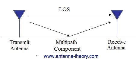
I have unfortunately learned that hallways behave as giant waveguides, so my results were not spectacular. In a hallway, the multipathing effect is very high, so after certain distances away from the transmitter, the receiver begins to hear the same signal reflected back into itself, amplifying the value.

This is very bad for trying to estimate distance because you can't get any information out of the data because it doesn't attenuate as you move farther from the source as it would in free space. The following chart shows my results from the hallway test:

As you can see, the data is all over the place. However, multipathing was not the only problem in the test environment. I needed to reverse calculate the path-loss exponent by using the distance formula to solve for n by plugging in measured RSSI values at known distances. After changing the path loss exponent to 2, the following values were obtained:
This new n value caused less fluctuation in distance estimation results, but as the multipathing effect caused the signal to attenuate very slowly, it became indistinguishable at larger distances. I also took fewer data points having realized the hallway was going to produce these results.

I plan to test this code again in a large, open space, so be sure to check back later for those results!

Thursday, April 10, 2014

Using the XBee Library with Atmel Studio 6

Now that the library is coming together, I thought it would be useful to write up a quick tutorial on how to use the library, and elaborate a little more on the structure.

The test platform I initially used when developing this code is shown below:


Although an arduino board was used, the arduino bootloader was not. However, since the arduino compiler uses avr-gcc, the library can still be included with arduino code. The ISP programming pins are available on the arduino, and any ISP programmer can be used to upload c code to the Atmega328p microcontroller. I used the AVRISP MKII, which can be purchased from mouser for around 40 bucks.


I prefer the AVRISP MKII, although it is more expensive than 3rd party programmers, it is almost always guaranteed to work with Atmel studio software.

Now, I will create a new project in Atmel Studio 6:


Remember to select the proper AVR if you are using something other than an arduino uno. Since I'm using the uno, I've selected the Atmega328p. After the new project is created, I will copy the XbeeS2.c, XbeeS2.h, and XbeeHAL.h files into the same directory as the .c file with main(). After the files have been added, be sure to add the files to the project:


Once the files are added, be sure to #include "XbeeS2.h". Before compiling, the only file the user needs to edit to use the library is XbeeHAL.h. XbeeHAL contains all the hardware specific abstractions. At the time of writing this tutorial, the Atmega328p and Atmega2560 is supported. If you are also using the Atmega328p, you just have to make sure that "ATmega328P" is #defined. If you are using a different micro, there are a few functions to define that are necessary for the library to function properly.

  • XBEE_UDR - Xbee USART Data Register; This is macro'd to the Data Register Buffer of the USART that the microcontroller is using for interfacing with the Xbee.
  • TX_BUFFER_IS_FULL() - Normally macro'd to ((UCSR0A & (1 << RXC0)) == 0) for the ATmega328P, this is a simple function that is used to check if the UDR is ready to be written. Most USART modules on microcontroller include a bit in a configuration register that indicates when the register is clear, so just change it such that it is appropriate for your micro.
  • RX_BUFFER_IS_FULL() - Macro'd to ((UCSR0A & (1 << UDRE0)) == 0) for the ATmega328P, this is the same thing as TX_BUFFER_IS_FULL(), but indicates when new data is received on UDR rather than when UDR is available to be written.
  • TOGGLE_LED()/LED_OUTPUT() - A test led. This can be changed to whatever is appropriate for your setup, and may be removed from the library later. Not actually needed for proper functionality.
This covers the macros needed, but there are also 2 functions that need to be set in XbeeHAL.h.
  • ISR(USART_RX_vect) { rxISR(); } - This is strictly for AVR's, but the HAL needs to have access to your micro's USART ISR. All the ISR needs to do is call the rxISR() function from the Xbee.c file.
  • void USART_INIT(void) - This is a function just to set up the USART at whatever baud rate you want to specify. Just make sure it matches your Xbee's baud rate! ;)
That covers the hairy details. If you are using the Arduino UNO or ATmega328P, then all of those points can be ignored.


To use the library, the user must call XbeeUSART_init() first. Then, the user may call any function from the library, such at Zigbee_Transmit_Request() for sending messages. Also, a callback feature is available for when the user wants to perform some task when a new packet arrives. To do this, the user calls setNewPacketCB(), passing it the name of the function to be called when the new packet arrives. 


I hope this helps anyone who is looking to try out the library! I will post new revisions here as they come out! Remember, you should only have to modify the HAL, and all the functions available can be found in Xbee.h.

Thanks for reading!

XBee S2 HAL
XBeeS2.c
XBeeS2.h

UPDATE:
I have added more features and restructured some of the library's files. For the time being I will post a link here to the newest version, and later provide a tutorial and github link.
https://dl.dropboxusercontent.com/u/47687797/XBee%20Library.zip

Monday, April 7, 2014

Links to XBee Series 2 Code

Last post I had copied the XBee Series 2 Library code into the text itself, but now I have convenient links! They are still a work in progress, but feel free to give it a shot!

XBee S2 HAL
XBeeS2.c
XBeeS2.h