Distance Equation:
After searching all over the internet and the IEEE Xplore library, I have finally found an equation that works relatively well for RSSI/distance estimation from this journal article.
RSSI = -(10*n*log10(d) + A)
Where- RSSI is the RSSI value received (dBm)
- n is the path-loss exponent
- d is the distance
- A is the RSSI value at a reference distance
So what is the path-loss exponent? How do you select a value for A?
Path Loss Exponent:
The path loss exponent has to be determined experimentally. The path loss variable ranges from around 2 to 4, where 2 is the free-space value (no obstruction, line of sight) and 4 represents a very lossy environment. A simplified form of the model is represented below from wikipedia, however, a more detailed one can be found here.
 , where L is the path loss in dB, n is the path loss exponent, d is the distance between transceivers, and C is a constant which accounts for system losses.
This table from this Zigbee book gives sample path loss exponent values for common environments:

Selecting the Reference Value:
A can be found by measuring the RSSI value at whatever distance you want to reference. My measurements are taken in meters, so A is the RSSI value received when the receiver is 1 meter in front of the transmitter with no obstacles in between.
Implementation on XBee:
So far this has been all talk. Let's see how this works in a real environment.
I will be testing this formula out using XBee series 2 modules and these antennas (Digi P\N: A24-HASM-525). This antenna is important, as it is an omni-directional antenna; meaning it has a relatively uniform radiation patter. Most chip antennae have a very non-unimform radiation pattern, causing the RSSI value to fluctuate drastically due to the orientation of the nodes, rendering everything we are trying to do here useless.
My experimental setup involves two series 2 XBees, one coordinator and one end device. The end device is attached to a Sparkfun RedBoard (arduino clone). The coordinator is connected to my laptop using a Sparkfun XBee Xplorer board. The RedBoard is running code written using Atmel Studio and my XBee library which echos back to the sender the RSSI value and estimated distance.
I have set the following function to be called when a new packet arrives using "setNewPacketCB()". This function retrieves the RSSI value and applies the formula above to estimate distance and return it to the sender.
float A = -45.0; // Reference RSSI value at 1 meter
float n = 2.2; // Path-loss exponent
void newPacket()
{
RxPacket rx_data = getPacket();
// Echo rssi value back
int len = 1; // sprintf buffer length
float distance;
char buff[20];
char rssi = getRSSI();
if(rssi != 0xFF) // 0xFF is error code when value is not returned
{
// sign in front of rssi changed to positive because rssi value from XBee is negative
distance = pow(10.0,((A + rssi)/(10.0*n)));
len = sprintf(buff, "%d + %3f\n",(unsigned int)rssi, distance);
ZigBee_TX_Request(0,0,0xFFFF,rx_data.source_addr_16bit, 1, 0, buff, len);
}
}
For this code to work you will need to ensure that you are using the floating point math library and floating point version of printf. To compile properly in AVR/Atmel Studio:
- Go to Project->Properties (ALT+F7) and under AVR/GNU C++ Linker select Libraries. Under Libraries (-Wl,-l) use the Add button twice and insert libprintf_flt then libm
- Go to Miscellaneous and add -Wl,-u,vfprintf -lprintf_flt -lm
After downloading my code to the RedBoard and connecting the coordinator to the laptop, if I open up a terminal using X-CTU connected to the coordinator and hit enter, I get the following output:

Where 51 means the RSSI value received was -51 dBm and the estimated distance was 1.87 meters.
Before testing, I recorded the RSSI value at one meter away, which gave me a value of -45dBm. Plugging this into the A variable in my code and setting n to be 2.2 (Choosing the n value for a retail store from the chart since the building I'm working in is somewhat similar. Sadly, this was a terrible first guess) I downloaded the code and set up my laptop in the hallway of the EPIC building at UNCC. I placed sticky note markers at various lengths to move my end device to for measuring.
Results:
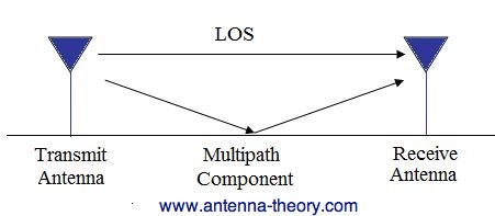
I have unfortunately learned that hallways behave as giant waveguides, so my results were not spectacular. In a hallway, the multipathing effect is very high, so after certain distances away from the transmitter, the receiver begins to hear the same signal reflected back into itself, amplifying the value.
This is very bad for trying to estimate distance because you can't get any information out of the data because it doesn't attenuate as you move farther from the source as it would in free space. The following chart shows my results from the hallway test:

As you can see, the data is all over the place. However, multipathing was not the only problem in the test environment. I needed to reverse calculate the path-loss exponent by using the distance formula to solve for n by plugging in measured RSSI values at known distances. After changing the path loss exponent to 2, the following values were obtained:

I plan to test this code again in a large, open space, so be sure to check back later for those results!
two zigbees at 1 meter distance without obstacle, received RSSI value is FF ?? what could the error ?
ReplyDeleteIf you are using my library, FF is an error code that happens when you request the RSSI, but the Xbee never returns the AT response frame. In my newer versions of the Xbee library, which I will hopefully be posting soon, I am turning off global interrupts at the beginning of the getRSSI() function. If you are using an AVR microcontroller try putting cli(); at the top of that function and sei(); before the return and see if that makes it work any better.
DeleteWhen I was developing the code, I had a lot of problem requesting AT commands and never getting the response frame back.
Can i use xbee series 1 for the setup?
ReplyDeleteYes you can! It's actually much easier since the RSSI value is included in each Series 1 API packet.
Deletehi, may i ask how to get the value of estimated distance 1.87 meter, i use your equation and calculate using calculator i get 10^4.3636=21047.47
ReplyDeleteHi! I just ran the numbers and I'm honestly not sure how I got that number! :S It was some time ago now, and I can't offer an exact reason. (Perhaps the code I ran had a different 1m path loss variable than the one displayed) But, in your calculation, don't forget that the RSSI values and path loss value are negative! That will give you more reasonable approximations.
DeleteWhat does the constant "C" System Loss refers to?
ReplyDeleteIt's been a while since I wrote this, so I guess I should go back and update some terms. The source I originally used for that model called C the "system loss". From further reading, that is used as a reference of path loss per unit of measurement. For example, if you are using meters as your unit of distance, C would be the RSSI value 1 meter away from the source.
DeleteSir, I have three zigbee series 2, one as coordinator and two as router, then I will have a Bluetooth device connected as rssi, will I be able to detect the device location?
ReplyDeleteIf you can get bluetooth to communicate to the xbee modules, you can. I've not done much with bluetooth, so if you can get the protocols to talk and acquire the RSSI value, then you can using the model presented here. If you are in free space (no clutter, line-of-sight, no reflective materials surrounding the devices) you can get around 1 meter's worth of accuracy. Other techniques will be required to get a more precise location value.
Deletegood
ReplyDeletevery good information
ReplyDeletehighly useful
how can i fix the value of rssi that it will spike
ReplyDeletethat it will not spike...
Deletei use measuring tool to mark a floor so that it will be my reference for distance.. at first in testing 5meters it is actually giving me a 5.21 meters but then if the distance is further like 10meters the xbee is giving me random distance about 15meters to 20meters how can i solve the problem
While i just had become within your online site while sporting specified recognition comfortably a lot of touch submits. Amiable technique for outlook, I will be book-marking at present need devices gain spgs best suited all the way up. distance calculator UK
ReplyDelete