Labels

Showing posts with label RSSI. Show all posts

Friday, May 30, 2014

Estimating Distance from RSSI Values using XBee

Another really fun thing to do in wireless networks is finding your distance from another transceiver using signal strength values. Because of noise, multipathing, and various things that impede wireless signals (such as fleshy, water-filled human bodies), it is impossible to get very fine-grain estimations from RSSI values alone. From my research, it seems that a resolution of ~1m is as good as it gets. Which means if you don't have a good equation modeling the environment in which your network is deployed, your results will be horrible.

Distance Equation:

After searching all over the internet and the IEEE Xplore library, I have finally found an equation that works relatively well for RSSI/distance estimation from this journal article.

RSSI = -(10*n*log10(d) + A)
Where
  • RSSI is the RSSI value received (dBm)
  • n is the path-loss exponent
  • d is the distance
  • A is the RSSI value at a reference distance
So what is the path-loss exponent? How do you select a value for A?

Path Loss Exponent:

The path loss exponent has to be determined experimentally. The path loss variable ranges from around 2 to 4, where 2 is the free-space value (no obstruction, line of sight) and 4 represents a very lossy environment. A simplified form of the model is represented below from wikipedia, however, a more detailed one can be found here.

 L = 10\ n\ \log_{10}(d)+C, where L is the path loss in dB, n is the path loss exponent, d is the distance between transceivers, and C is a constant which accounts for system losses.

This table from this Zigbee book gives sample path loss exponent values for common environments:


Selecting the Reference Value:

A can be found by measuring the RSSI value at whatever distance you want to reference. My measurements are taken in meters, so A is the RSSI value received when the receiver is 1 meter in front of the transmitter with no obstacles in between.

Implementation on XBee:

So far this has been all talk. Let's see how this works in a real environment.

I will be testing this formula out using XBee series 2 modules and these antennas (Digi P\N: A24-HASM-525). This antenna is important, as it is an omni-directional antenna; meaning it has a relatively uniform radiation patter. Most chip antennae have a very non-unimform radiation pattern, causing the RSSI value to fluctuate drastically due to the orientation of the nodes, rendering everything we are trying to do here useless.

My experimental setup involves two series 2 XBees, one coordinator and one end device. The end device is attached to a Sparkfun RedBoard (arduino clone). The coordinator is connected to my laptop using a Sparkfun XBee Xplorer board. The RedBoard is running code written using Atmel Studio and my XBee library which echos back to the sender the RSSI value and estimated distance.

I have set the following function to be called when a new packet arrives using "setNewPacketCB()". This function retrieves the RSSI value and applies the formula above to estimate distance and return it to the sender.

float A = -45.0; // Reference RSSI value at 1 meter
float n = 2.2; // Path-loss exponent


void newPacket()
{
RxPacket rx_data = getPacket();
// Echo rssi value back
int len = 1; // sprintf buffer length
float distance;
char buff[20];
char rssi = getRSSI();
if(rssi != 0xFF) // 0xFF is error code when value is not returned
{
// sign in front of rssi changed to positive because rssi value from XBee is negative
distance = pow(10.0,((A + rssi)/(10.0*n)));
len = sprintf(buff, "%d + %3f\n",(unsigned int)rssi, distance);

ZigBee_TX_Request(0,0,0xFFFF,rx_data.source_addr_16bit, 1, 0, buff, len);
}
}

For this code to work you will need to ensure that you are using the floating point math library and floating point version of printf. To compile properly in AVR/Atmel Studio:

  1. Go to Project->Properties (ALT+F7) and under AVR/GNU C++ Linker select Libraries. Under Libraries (-Wl,-l) use the Add button twice and insert libprintf_flt then libm
  2. Go to Miscellaneous and add -Wl,-u,vfprintf -lprintf_flt -lm

After downloading my code to the RedBoard and connecting the coordinator to the laptop, if I open up a terminal using X-CTU connected to the coordinator and hit enter, I get the following output:


Where 51 means the RSSI value received was -51 dBm and the estimated distance was 1.87 meters.

Before testing, I recorded the RSSI value at one meter away, which gave me a value of -45dBm. Plugging this into the A variable in my code and setting n to be 2.2 (Choosing the n value for a retail store from the chart since the building I'm working in is somewhat similar. Sadly, this was a terrible first guess) I downloaded the code and set up my laptop in the hallway of the EPIC building at UNCC. I placed sticky note markers at various lengths to move my end device to for measuring.

Results:

I have unfortunately learned that hallways behave as giant waveguides, so my results were not spectacular. In a hallway, the multipathing effect is very high, so after certain distances away from the transmitter, the receiver begins to hear the same signal reflected back into itself, amplifying the value.
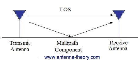
This is very bad for trying to estimate distance because you can't get any information out of the data because it doesn't attenuate as you move farther from the source as it would in free space. The following chart shows my results from the hallway test:

As you can see, the data is all over the place. However, multipathing was not the only problem in the test environment. I needed to reverse calculate the path-loss exponent by using the distance formula to solve for n by plugging in measured RSSI values at known distances. After changing the path loss exponent to 2, the following values were obtained:
This new n value caused less fluctuation in distance estimation results, but as the multipathing effect caused the signal to attenuate very slowly, it became indistinguishable at larger distances. I also took fewer data points having realized the hallway was going to produce these results.

I plan to test this code again in a large, open space, so be sure to check back later for those results!

Saturday, August 3, 2013

Xbee Series 2 RSSI Bug

For those of you who didn't read the last post, be sure to look at it here before reading this one, because
otherwise it doesn't make any sense!
http://stupidembeddedblog.blogspot.com/2013/07/getting-rssi-from-xbee-series-2.html

I have been wrestling with this stupid "bug" for the past week, and just before losing my last bit of sanity I discovered my problem and I feel it is appropriate to post it here. Last entry we had looked at how to retrieve the RSSI value from an Xbee series 2 module and some code to obtain it with as well.

Source
In my sensor network, I have each node periodically broadcast a message to all nodes within 1 hop, and the receiving nodes then obtain the sender's 16 bit address and the RSSI of the packet, then sends that back to the coordinator along with it's own 16 bit address. The coordinator is connected to a PC running MATLAB which then uses the information to localize the nodes using triangulation.

The problem I was having was after a brief period of time, when using the code from the previous post to obtain the RSSI, the code would get stuck after the DB AT command was issued. I couldn't figure out what was going on because most of the time the code worked, but it would lock up after at least 3 other nodes were on the network, constantly bombarding each other with packets. At first I was suspicious an interrupt was causing the problem, but that was not the case.

The Xbees store a message queue, and despite issuing the AT command and expecting the appropriate response frame back immediately, instead I was getting the Zigbee receive frame from a previously received message. This caused the code to get stuck waiting for certain parts of an expected frame that it wasn't going to received.

Here's the updated code!

char getRSSI(void)
{
RxPacket pkt;
int temp;

do 
{
AT_Command(0x01, 'D', 'B', 0, 0); // Send DB AT Command
while ((UCSR0A & (1 << RXC0)) == 0){};
temp = UDR0;
receive_Msg(&pkt);
} while (pkt.api_identifier != 0x88);

printf("RSSI is %d\n", pkt.data[0]);
return pkt.data[0]; // Return RSSI value
}

In this code we use the receive message command to obtain the packet, then check to see if the frame received was an AT response. If not, then we simply request it again. This may not be perfect, but for now, it works! Also, the new packet function was removed from the receive_Msg() function and added to the USART ISR which now looks like this:

ISR(USART_RX_vect) 
{   
PORTD ^= 0x80; // TEST LED
if(UDR0 == 0x7E)
{
receive_Msg(&rx_pkt);
newPacketRX(&rx_pkt); // Call function for responding to new packet
}

PORTD ^= 0x80; // TEST LED
}

So this is it for now. Subscribe for future updates!

Saturday, July 27, 2013

Getting RSSI from Xbee Series 2

This has been one of the most obnoxious endeavors I've taken on so far with Xbees. For those of you who might be familiar with the API mode of the Xbee series 1, each packet includes the RSSI (Received Signal Strength Indicator) value in it. In series 2 that is not the case. I'm not sure what the reasoning is behind excluding that byte from the packet, but I suspect that it has something to do with only reflecting the strength of the last hop, and in a multihop network that may be considered "useless", but whatever.

I scoured the internet looking for other solutions. Most sites I found mentioned that you can turn on the PWM (Pulse Width Modulation) output on pin6 to reflect the RSSI value. This was mostly designed with the intention of hooking up a cute little LED that glows brighter according to the signal strength. When the RSSI PWM is enabled, a signal is output on pin 6 which has a duty cycle that ranges from 24% to 100%.

According to the documentation:

 Zero percent means PWM output is inactive. One to 24% percent means the received RF signal is at or below the published sensitivity level of the module. The following table shows levels above sensitivity and PWM values.

dB above Sensitivity - Dutycycle 
10   -  41%
20   -  58%
30   -  75%


The total period of the PWM output is 64 μs. Because there are 445 steps in the PWM output, the
minimum step size is 144 ns.

A non-zero value defines the time that the PWM output will be active with the RSSI value of the
last received RF packet. After the set time when no RF packets are received, the PWM output will
be set low (0 percent PWM) until another RF packet is received. The PWM output will also be set
low at power-up until the first RF packet is received. A parameter value of 0xFF permanently
enables the PWM output and it will always reflect the value of the last received RF packet.

The next step was to find a legitimate conversion rate from this stupid PWM output to dB. I stumbled upon the following excerpt from some random forum:
DB parameter is used to read the received signal strength (in dBm) of the last RF packet received. Reported values are accurate between -40 dBm and the RF module's receiver sensitivity.

Parameter Range [read-only]: 0x17-0x5C (XBee), 0x24-0x64 (XBee-PRO)
Absolute values are reported. For example: 0x58 = -88 dBm (decimal). If no packets have been received (since last reset, power cycle or sleep event), “0” will be reported.

So I suppose I could map the sensitivity range to 24% to 100% duty cycle, but I came across a much better solution, the DB AT command!

Seems like a very obvious solution, but what I was reading at most websites was that it takes at least 2 seconds to retrieve the value. To enter "command mode" on most Xbees, you must wait 2 seconds, send "+++", the command to enter command mode, then send "ATDB\r" and wait for the response. I was used to working with the Xbee S1 modules in API mode, which issues AT commands the same way, by send the "+++" code and junk, so I assumed S2 is the same way and immediately dismissed that as a viable option. Who has 2 seconds to sit around and do nothing but miss packets!?

Turns out, if you are using Xbee series 2 API firmware, AT commands are not accessed by sending the "+++" command. You send an API frame that is structured for AT commands. This means you don't have to wait 2 seconds to receive the dB! However, this does mean I needed to seriously modify my code, because now we are using another type of API packet! The following function was written:

void AT_Command(char frameid, char command1, char command2, char *options, int len)
{
char buff[5]; //temporary buffer for transmitting
int count;
buff[0] = 0x08; // API ID for AT Commands
buff[1] = frameid; // Frame ID; set to 0 for no response
buff[2] = command1;
buff[3] = command2;
for(count = 1; count <= len; count++)
buff[3 + count] = options;
send_Msg(buff, 4 + len);
}

In this function you pass the frame ID, the two characters for the AT command (e.g., 'D' and 'B'),  and any options that may go along with that in the form of an array, and the length of that array. Those values are then sent to our send_Msg() function we discussed last post.

We also had to make a few modifications to receive the packets from AT commands if they return information such as the DB command. To hold this, our data structure for Xbee frames was modified:

typedef struct{
int len;
char api_identifier;
long DH;
long DL;
int source_addr_16bit;
char options;
char frame_id;
char AT_com[2];
char status;
char data[20]; // also stores the "value" for at command response
char checksum;
} RxPacket;

We've added the frame_id, AT_com[], status, and options for receiving AT returned frames. Inside the switch statement of our receive_Msg() function we've added the following case:

case 0x88: // AT Command
for(count = 1; count < rx_data->len; count++)
{
while ((UCSR0A & (1 << RXC0)) == 0) {}; // Do nothing until data have been received and is ready to be read from UDR
if(count == 1)
rx_data->frame_id = UDR0;
else if(count == 2)
rx_data->AT_com[0] = UDR0;
else if(count == 3)
rx_data->AT_com[1] = UDR0;
else if(count == 4)
rx_data->status = UDR0;
else
rx_data->data[count - 5] = UDR0;
}
while ((UCSR0A & (1 << RXC0)) == 0) {}; // Do nothing until data have been received and is ready to be read from UDR
rx_data->checksum = UDR0; //store checksum
break;

Now we can receive AT Commands! Now to look at the function I've written to specifically request the dB:

char getRSSI(void)
{
RxPacket pkt;

AT_Command(0x01, 'D', 'B', 0, 0); // Send DB AT Command
cli();

int count, len;
char temp, checksum;

while ((UCSR0A & (1 << RXC0)) == 0) {}; // Do nothing until data have been received and is ready to be read from UDR
temp = UDR0;

while ((UCSR0A & (1 << RXC0)) == 0) {}; // Do nothing until data have been received and is ready to be read from UDR
temp = UDR0; //next incoming byte is the MSB of the data size
while ((UCSR0A & (1 << RXC0)) == 0) {}; // Do nothing until data have been received and is ready to be read from UDR

pkt.len = (temp << 8) | UDR0; //merge LSB and MSB to obtain data length
while ((UCSR0A & (1 << RXC0)) == 0) {}; // Do nothing until data have been received and is ready to be read from UDR
pkt.api_identifier = UDR0;

for(count = 1; count < pkt.len; count++)
{
while ((UCSR0A & (1 << RXC0)) == 0) {}; // Do nothing until data have been received and is ready to be read from UDR
if(count == 1)
pkt.frame_id = UDR0;
else if(count == 2)
pkt.AT_com[0] = UDR0;
else if(count == 3)
pkt.AT_com[1] = UDR0;
else if(count == 4)
pkt.status = UDR0;
else
pkt.data[count - 5] = UDR0;
}
while ((UCSR0A & (1 << RXC0)) == 0) {}; // Do nothing until data have been received and is ready to be read from UDR
pkt.checksum = UDR0; //store checksum

//printf("RSSI is %d\n", pkt.data[0]);
sei();

return pkt.data[0]; // Return RSSI value
}

I didn't actually end up using the receive_Msg() function for acquiring the dB, but the functionality is still there in case it's needed later. This getRSSI() function simply returns the dB value, just remember that the value is actually negative because it is the dB of the signal loss!